Reference/Code: ASTM C 1479-10
Safety:
-
WARNING: Erecting concrete elements is a
high risk activity. Adequate safety controls must be in
place in conformance with legislation and codes of practice.
-
A risk assessment must be carried out by the contractor
identifying all risks/hazards and measures to control or
eliminate the identified risks/hazards. A safe work method
statement (SWMS) must be prepared before the high risk
construction activity commences.
-
The appropriate personal protective equipment (safety
eyewear, gloves, hardhats, hi-visibility vests and safety
footwear) is to be worn during all stages of installation of
concrete elements.
-
Equipment shall be fit for its intended purpose and
operating conditions and shall be designed to a recognized
standard.
Offloading / Handling
-
The Pipe should be visually inspected on the truck when it
arrives at the jobsite before it is unloaded to ensure that
no damage has occurred during transit.
-
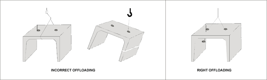
When handling concrete products, it is important to remember
that, as concrete is a heavy and somewhat brittle material,
bumps or shock loads of any description are liable to damage
the product. This applies particularly to sharp edges.
-
All offloading areas provided must be level, hard, drained
and free of debris.
-
Any Pipe is damaged during transit or offloading should be
marked and set aside.
-
Damaged ends, chips or cracks which do not pass through the
wall can easily be repaired. These products should be
clearly marked to ensure that the necessary repairs are done
before installation.
-
Pipe can be offloaded with conventional lifting. However,
specialized equipment with safe lifting capacity is
recommended.
-
The offloading of Pipe must be controlled to prevent
collision with other Pipe or hard objects.
-
If Pipe have to be moved long distances from the storage
area to the site where they are to be installed, they should
be transported in the same way as AOCP delivered them to
site.
Storage/Stacking
Double handling should be avoided. However, where the site
conditions do not permit, a storage yard away from the laying site
will have to be established. The product may then be received at
the storage yard and transported to the laying site when
required.
The storage area should be level, firm and clear of any objects
that may cause damage to the products.
Storage area clear of combustible materials and free from storm
water flooding should be selected.
Any storage of products should be as near as possible to where the
products will be installed.
If Pipe have to be moved long distances from the storage area to
the site where they are to be installed, they should be
transported in the same way as the AOCP delivered them to site.
Site Preparation
Site preparation can significantly influence progress of the
project. The amount and type of work involved in site preparation
varies with the location of the project, topography, surface
conditions, and existing utilities. Commonly included are:
- Detours and traffic control signing
- Access roads
Clearing and grubbing
- Tree relocation or protection
- Stripping and stockpiling topsoil
- Pavement and sidewalk removal
- Management of excess material
- Relocation of existing natural drainage
-
Notifications and protection of existing structures and all
utilities
-
Environmental considerations, such as temporary erosion and
sediment control.
Product Installation
Line and Grade
For sewer construction, where the pipe is installed in a trench,
line and grade are usually established by one, or a combination of
the following methods:
-
Control points consisting of stakes and spikes set at the
ground surface, and offset a certain distance from the
proposed sewer centerline
-
Control points established at the trench bottom, after
- The trench is excavated
-
Trench bottom and pipe invert elevations established while
excavation and pipe installation progresses
- Global Positioning System (GPS)
Important
Line and grade should be checked as the pipe is installed, and
any discrepancies between the design and actual alignment and
pipe invert elevations should be corrected prior to placing the
backfill or fill over the pipe.
Obtaining manhole invert levels for the preparation of as- built
drawings, combined with visual inspection of the sewer or
culvert, provide an additional check that settlement has not
occurred during backfill or fill operations.
Where control points are established at the surface and offset,
lasers, transits, batter boards, tape and level, or specially
designed transfer instruments, are used to transfer line and
grade to the trench bottom. Regardless of the specific type of
transfer apparatus used, the basic steps are:
-
Stakes and spikes, as control points, are driven flush
with the ground surface at 7.5 to 15m intervals for
straight alignment, with shorter intervals for curved
alignment.
-
Offset the control points 3m, or another convenient
distance, on the opposite side of the trench from which
excavated material will be placed.
-
Determine control point elevations by means of a level,
transit or other levelling device. Drive a guard stake to
the control point, and mark the depth of the control point
from the control point to the trench bottom or pipe
invert.
-
After the surface control points are set, a grade sheet is
prepared listing reference points, stationing, offset
distance and vertical distance from the control points to
the trench bottom or pipe invert.
Transferring the line and grade along the trench bottom is
achieved by using a laser system, or a batter board system.
The laser system, the most commonly used system, uses a
transit or level to set the starting point on the trench
bottom. As with any surveying instrument, the initial setting
is most important. Once the starting point is established, the
laser can be set for direction and grade. Lasers can be used
for distances up to 300 m (average runs for pipe installations
are 90 to 150 m). The projected beam is intercepted along the
trench bottom with a target, placed in the bell that accepts
the light.
Temperature can affect the trueness of the laser beam;
therefore, it is helpful to keep the line well ventilated. The
laser instrument can be mounted in a maintenance hole, set on
a tripod or placed on a solid surface to project the light
beam either inside, or outside the pipe. A workman with any
ordinary rule, or stadia rod, can measure offsets quickly and
accurately, generally within 2 mm or less.
There are two types of batter board systems. One type is
incorporated for narrow trenches, the other for wide
trenches.
For narrow trenches, a horizontal batter board is spanned
across the trench, and adequately supported at each end. The
batter board is set level at the same elevation as the string
line, and a nail driven in the upper edge, at the centre line
of the pipe. In many cases the batter board is used only as a
spanning member, with a short vertical board nailed to it at
the pipe centerline. A string line is pulled tight across a
minimum of three batter boards, and the line transferred to
the bottom by a plumb bob cord held against the string line.
Grade is transferred to the trench bottom by means of a grade
rod, or other suitable vertical measuring device.
Where wide trenches are necessary, due to large pipe sizes or
sloped trench walls, the batter board may not be able to span the
width of excavation. In such cases, the same transfer principle is
used, except that the vertical grade rod is attached to one end of
the batter board, and the other end set level against the offset
string line. The length of horizontal batter board is the same as
the offset distance. The length of the vertical grade rod is the
same as the distance between the pipe invert and the string
line.
Specially designed instruments are available which incorporate a
measuring tape, extendible arm and levelling device. These
instruments are based on the same principle, but eliminate the
need to construct batter boards and supports.
Equipment
Several types of excavating equipment are available. Selection of
the most efficient piece of equipment for a specific excavation
operation is important, since all excavating equipment has
practical and economic limitations. Considerations include the
type and amount of material to be excavated, depth and width of
excavation, dimensional limitations established in the plans, pipe
size, operating space and spoil placements. Basic equipment can
usually be modified or adapted for use in most excavating
operations.
Excavation
For sewer construction, the scope of operations involved in
general excavation includes trenching, tunnelling, backfilling,
embankment construction, soil stabilization, and control of ground
water and surface drainage. Adequate knowledge of subsurface
conditions is essential for any type of excavation.
This is accomplished through soil surveys and subsequent soil
classification. Soil borings are usually obtained for design
purposes, and the information included on the plans, or made
available to the contractor in a separate document. This soil
boring information is useful in evaluating unsuitable subsoil
conditions requiring special construction. If the subsoil
information on the plans is not sufficiently extensive, it is
normally the responsibility of the contractor to obtain additional
test borings.
Excavated Material
The placement of excavated material is an important consideration
in sewer construction, and may influence the selection of
excavating equipment, the need of providing sheathing and shoring,
and backfill operations.
In trench installations, the excavated material is usually used
for backfill, and should be placed in a manner that reduces
re-handling during backfilling operations. As a general rule, for
unsupported trenches, the minimum distance from the trench to the
toe of the spoil bank should not be less than one half the trench
depth. For supported trenches, a minimum of one metre is normally
sufficient.
Stockpiling excavated material adjacent to the trench causes a
surcharge load, which may cave in trench walls.
The ability of the trench walls to stand vertically under this
additional load depends on the cohesion characteristics of the
particular type of material being excavated. This surcharge load
should be considered when evaluating the need to provide trench
support. It may be necessary, where deep or wide trenches are
being excavated, to haul away a portion of the excavated soil, or
spread the stockpile with a bulldozer, or other equipment. If the
excavated material is to be used as backfill, the stockpiled
material should be visually inspected for rocks, frozen lumps,
highly plastic clay, or other objectionable material.
If the excavated soil differs significantly from the backfilled
material set forth in the plans, it may be necessary to haul the
unsuitable soil away and bring in selected backfill material.
Spoil placement for culvert installations is usually not as
critical as trench installation. If the excavated material is
suitable for the embankment construction, it can be immediately
incorporated into the embankment adjacent to the culvert. If using
imported materials, care must be taken so that the frost
susceptibility is the same as the native material. Top soil, or
other highly organic soils, are usually stockpiled outside the top
of the embankment slope, and used for dressing the slopes after
the embankment is constructed.
Dewatering
Dewatering of trenches and excavations should be undertaken in
order to keep the excavation stable and free of water. Dewatering
efforts must be monitored for impacts such items as settlement and
ground water usage. When dewatering efforts are no longer required
they must be arrested such that no disturbance to the pipe will
occur.
Water from dewatering operations must be disposed of in accordance
with local regulations. Pumped water requires that it be filtered
through a sediment control device and disposed of such that it
does not impact public health or safety, property or the
environment. Water should not be directed over pavements or
sidewalks or effect the functionality of settling ponds and
sediment basins.
Excavation Limits
It is the contractor's responsibility to adhere to all
Occupational Health and Safety Act requirements for excavations.
The sloping requirements for Soil shall follow as per drawings.
In general no more than 15 m of trench be open in advance of the
completed pipe system.
The most important excavation limitations are trench width and
depth. As excavation progresses, trench grades should be
periodically checked against the elevations established on the
sewer profile.
Improper trench depths can result in high or low spots in the
line, which may adversely affect the hydraulic capacity of the
sewer, and require correction, or additional maintenance, after
the line is completed. If the trench depth is excavated beyond the
limits of the required excavation, granular material should be
placed and compacted in the trench to reinstate the required
trench limits prior to backfilling the trench.
The backfill load transmitted to the pipe is directly dependent on
the trench width at the crown of the pipe. To determine the
backfill load, the designer assumes a certain trench width, and
then selects pipe strength capable of withstanding this load. If
the constructed trench width exceeds the maximum trench width
specified in the design, the pipe may be overloaded and may
require the use of a stronger pipe or a higher class of bedding,
or both. Where maximum trench widths are not indicated in any of
the construction contract documents, trench widths should be as
narrow as possible, with side clearance adequate enough to ensure
proper compaction of backfill material at the sides of the
pipe.
When unstable soil conditions are encountered, sheathing or
shoring can be used, or the banks of the trench can be sloped to
the natural angle of repose of the native soil. If the trench
sides are allowed to slope back, the pipe should be installed in a
shallow sub trench excavated at the bottom of the wider trench.
The depth of the sub trench should be at least equal to the
vertical height of the pipe.
For a confined trench installation, the following trench widths at
the top of the pipe are recommended:
|
CLEARANCE TABLE
|
Pipe Inside Diameter
(mm)
|
Clearance
(mm)
|
| 900 or less |
300 |
| Over 900 |
500 |
Sheathing and Shoring
Trench stabilization is usually accomplished through the use of
sheathing and shoring. The structural requirements of sheathing
and shoring depend on numerous factors such as:
- Depth and width of excavation
- Characteristics of the soil
- Water content of the soil
- Weather conditions
- Proximity to other structures
- Vibration from construction equipment or traffic
- Soil placement or other surcharge loads
- Code requirements
Accurate evaluation of all of these factors is usually not
possible, so the design and application of temporary bracing
systems varies considerably. However, certain methods of
stabilizing open trenches have evolved and can be used as a
general guide.
Shoring for trenches is accomplished by bracing one bank against
the other; structural members which transfer the load between the
trench sides are termed struts. Wood planks placed against the
trench walls to resist earth pressure, and retain the vertical
banks, are termed sheathing. The horizontal members of the bracing
system, that forms the framework bearing against the sheathing or
termed whalers or stringers, and the vertical members of the
bracing system are termed strong backs.
Improper removal of sheathing can reduce the frictional effects,
and increase the backfill load on the pipe, so sheathing should be
removed in increments, as the backfill is placed. Additional
compaction of the backfill material may be necessary to fill the
voids behind the sheathing, as it is removed. The four common
sheathing methods are:
- Open sheathing
- Close sheathing
- Tight sheathing
- Trench shields or boxes
Open Sheathing
Open sheathing consists of a continuous frame, with vertical
sheathing planks placed at intervals along the open trench. This
method of sheathing is used for cohesive stable soils, where
groundwater is not a problem.
Close Sheathing
Close sheathing consists of a continuous frame, with vertical
sheathing planks placed side by side to form a continuous
retaining wall. This method of sheathing is used for non-cohesive
and unstable soils.
Tight Sheathing
Tight sheathing is similar to closed sheathing, except the
vertical sheathing planks are interlocked. This method of
sheathing is used for saturated soils. Steel sheet piling is
sometimes used instead of wood planking.
Trench Boxes
Trench boxes, or shields, are heavily braced boxes of steel, or
wood, which can be moved along the trench bottom as excavation and
pipe laying progress. Trench boxes are used to protect workers
installing pipe in stable ground conditions, where the trenches
are deep and not sheathed. Trench shields are also used in lieu of
other methods of shoring and sheathing for shallow excavations
where the sides of the shields can extend from the trench bottom
to ground surface. When trench shields are used, care should be
taken when the shield is moved ahead, so as not to disturb the
bedding or pull the pipe apart.
Foundation Preparation
A stable and uniform foundation is necessary for satisfactory
performance of any pipe. The foundation must have sufficient load
bearing capacity to maintain the pipe in proper alignment and
sustain the mass of the backfill, or fill material placed over the
pipe. The trench bottom foundation should be checked for hard or
soft spots, due to rocks or low load-bearing soils. Where
undesirable foundations exist, it should be stabilized by
ballasting, or soil modification.
Ballasting requires removal of the undesirable foundation material
and replacing it with select materials such as sand, gravel,
crushed rock, slag, or suitable earth backfill. The depth,
gradation, and size of the ballast depend on the specific material
used and the amount of stabilization required, but usually the
ballast should be well graded.
Soil modification involves the addition of select material to the
native soil. Crushed rock, gravel, sand, slag, or other durable
inert materials with a maximum size of 75 mm, is worked into the
subsoil to the extent necessary to accomplish the required
stabilization.
In rock, shale or other hard, unyielding soils, the excavation
should be continued below grade, and the over-excavation replaced
with select material to provide a cushion for the pipe.
Pipe Bedding
Once a stable and uniform foundation is provided, it is necessary
to prepare bedding in accordance with the bedding requirements set
forth in the plans, specifications or standard drawings.
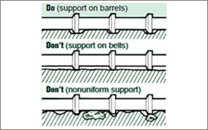
An important function of the bedding is to level out any
irregularities in the foundation, and assure uniform support along
the barrel of each pipe section. The bedding is also constructed
to distribute the load bearing reaction, due to the mass of the
backfill or fill material, around the lower periphery of the pipe.
The structural capacity of the pipe is directly related to this
load distribution, and several types of bedding have been
established to enable the specification of pipe strengths during
the design phase.
The following general requirements should be followed:
-
When bell and spigot pipe is to be laid, recesses should be
shaped to receive the bells.
-
Bedding material placed in the haunches must be compacted
prior to continued placement of cover material.
-
Bedding requiring compacting should be placed inlayers not
exceeding 200 mm in thickness, loose measurement, and
compacted to 95% of the max. Density before a subsequent
layer is placed.
-
Bedding on each side of the pipe should be completed
simultaneously. At no time should the levels on each side
differ by more than the 200 mm uncompacted layer.
For trench installations, where space is limited, tamping or
pneumatic and mechanical impact tampers kneading action, are
primarily useful for soils containing clays. Granular soils are
most effectively consolidated by vibration. Compaction equipment
can generate significant dynamic forces capable of damaging
installed pipe.
Bell holes should be excavated to accommodate projecting joints,
and to provide support along the barrel of the pipe.
Bedding Materials
Materials for bedding should be selected on the basis that uniform
contact can be obtained between the bed and the pipe. Since most
granular material will shift to attain this uniform contact as the
pipe settles, an ideal load distribution can be realized.
Bedding material is Granular in 25 mm or less in size, or
unshrinkable fill, as specified in the Contract documents.
Class B Bedding
Granular Foundation:
-
A granular foundation without shaping is used only with
circular pipe.
-
The pipe is bedded in compacted granular material placed on
the flat trench bottom.
-
The granular bedding has a minimum specified thickness, and
should extend at least half way up the pipe at the sides.
-
The remainder of the side fills, and a minimum depth of 300
mm over the top of the pipe, should be filled with densely
compacted material.
Shaped Sub grade:
-
For a shaped sub grade with granular foundation, the bottom
of the excavation is shaped to conform to the pipe surface
but at least 50 mm greater than the outside dimensions of
the pipe.
-
The width should be sufficient to allow 0.6 times the
outside pipe diameter for circular pipe, 0.7 times the
outside span for arch and elliptical pipe, and the full
bottom width of box sections to be bedded in fine granular
fill placed in the shaped excavation.
-
Densely compacted backfill should be placed at the sides of
the pipe to a depth of at least 300 mm above the top of the
pipe.
Class C Bedding
Granular Foundation:
-
Used only with circular pipe, the pipe is bedded in loosely
compacted granular material, or densely compacted backfill
placed on a flat bottom trench.
-
The bedding material should have a minimum specified
thickness, and should extend up the sides for a height of at
least 0.15 times the outside diameter.
-
For trench installations, the side fill and area over the
pipe to a minimum depth of 150 mm should be filled with
compacted backfill.
Shaped Sub grade:
-
The pipe is bedded with ordinary care in a soil foundation,
shaped to fit the lower part of the pipe exterior with
reasonable closeness for a width of at least 0.5 times the
outside diameter for a circular pipe, 0.15 times the outside
pipe rise for elliptical pipe, and full bottom width of box
units
-
For trench installations, the sides and area over the pipe
are filled with lightly compacted backfill to a minimum
depth of 150 mm above the top of the pipe.
-
For embankment installations, the pipe should not project
more than 90% of the vertical height of the pipe above the
bedding.
Cover
-
Cover material is Granular 25 mm or less in size, or native
material, as specified in the Contract Documents.
-
Cover material should be placed so that damage to or
movement of the pipe is avoided.
-
Cover material requiring compacting should be placed in
layers not exceeding 200 mm in thickness, loose measurement,
and compacted to 95% of the maximum dry density before a
subsequent layer is placed.
-
Cover material should be placed on each side of the pipe and
should be completed simultaneously. At no time should the
levels on each side differ by more than the 200 mm
uncompacted layers.
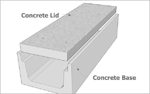
When single cell boxes are used in parallel for multi-cell
installations, positive lateral bearing must be provided between
the sides of adjacent units. This is accomplished with grout to
fill the 50mm annular space.
Backfill
-
Backfill material is Granular 25 mm or less in size, or
native material, as specified in the Contract Documents.
-
Backfill material should be placed in uniform layers not
exceeding 300 mm in thickness for the full width of the
trench and each layer should be compacted to 95% of the
maximum dry density before a subsequent layer is placed.
-
Backfill should be placed to a minimum depth of 900 mm above
the crown of the pipe before power operated tractors or
rolling equipment should be used for compacting. Uniform
layers of backfill material exceeding 300 mm in thickness
may be placed with the approval of the Contract
Administrator.
-
If the contract specifies native backfill material,
acceptable earth backfill material may be substituted with
the approval of the Contract Administrator.
-
In areas within the roadway, for a depth equal to the frost
treatment, the earth backfill material should have frost
susceptible characteristics similar to the adjacent
material.
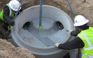
Handling
Proprietary lifting systems are used for various precast
concrete products, including pipe, maintenance holes, and box
units. These systems offer a positive lifting connection to the
pipe for added safety, and since the anchors are embedded,
patching is not required.
Important
The work procedures for material handling, worker safety, the
modification of backhoes for use as cranes and all components of
any lifting assembly must comply with the Occupational Health
and Safety Act requirements for Construction Projects. A
competent person designated by the contractor should inspect all
lifting assemblies and attachment hardware prior to each use.
Any damage or defective equipment must be immediately removed
from service. All other safety procedures and recommended
operating practices by the manufacturer of the lifting equipment
must be followed. Failure to observe the above warnings may lead
to property damage, personnel injury and death.
Load-Carrying Capacity of Lift Anchors
The MAXIMUM safe working load is clearly visible on the head of
the anchor for easy recognition of the appropriate hardware and
accessories for-use with the lift anchor. However the safe
working load of any lift anchor may be drastically reduced due
to several factors, such as:
- Length of anchor, or embedment depth
- Distance to edges, corners or openings
-
Concrete compressive strength at time of initial lift
- Number of lifting points and type of rigging used
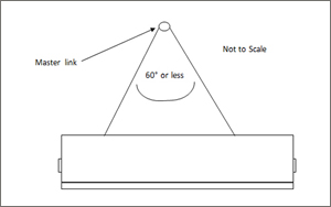
- Direction of pull (cable or sling angle)
- Impact or dynamic loads
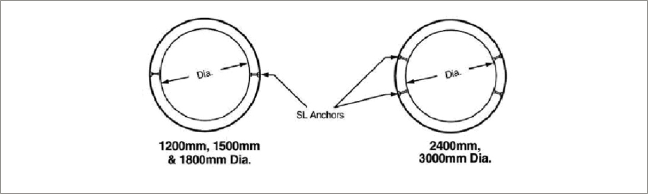
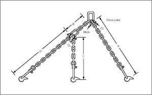
Handling Pipe
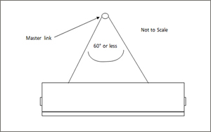
In pipe, anchors are placed laterally along the top of the pipe.
These anchors can accommodate pipe diameters from 975mm to
3600mm. Because the pipe is lifted by two points, stability
during lifting is established.
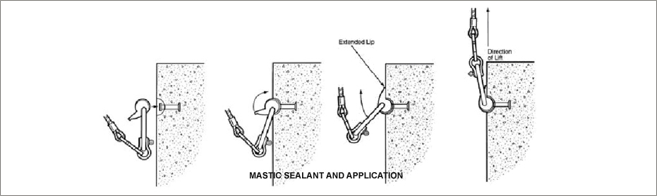
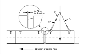
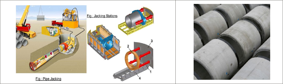
How to Use Lift Anchors for Setting Pipe
Lift anchors in concrete pipe can be used to "home" or pull the
product into its final position with a special chain sling such as
the P-74-S Pipe Laying Sling by Dayton Superior, shown below.
1. The pipe is first transported to the installation site with the
symmetrical sling and lowered close to the already placed pipe.
2. The long leg of the Pipe Laying Sling is attached to the
farthest anchor on the previously laid pipe. The free leg is
attached � out of the way � on the clevis link provided.
3. Locate the center of lift over the closest anchor of the
previously laid pipe. This will properly align the direction of
pull.
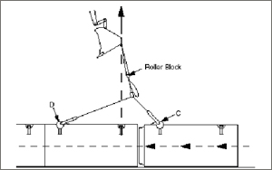
4. The pipe is pulled into position by slowly raising the boom on
the crane or backhoe without moving the boom forward or backward.
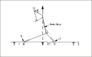
5. When the pipe has been pulled into position, the load is
released and the Pipe Laying System is moved to the next pipe, and
the process is repeated.
Warning: Anchors can become overloaded and fail
if the crane or back hole continues to apply load after the
connection has been completed.
Jointing
Pipe should be lowered into the trench, or set in place for
embankment installations, with the same care as when the pipe was
unloaded from the delivery trucks.
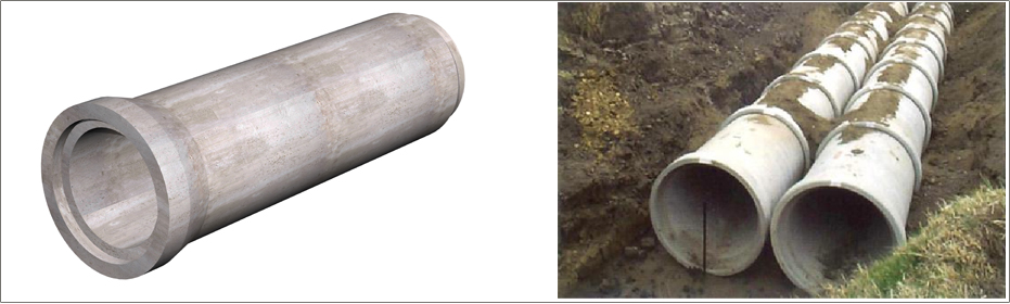
In laying the pipe, it is general practice to face the bell end of
the pipe in the upstream direction. This placing helps prevent
bedding material from being forced into the bell during jointing,
and enables easier coupling of pipe sections.
Jointing Materials
Several types of joints and sealant materials are utilized for
concrete pipe, to satisfy a wide range of performance
requirements. All of the joints are designed for ease of
installation. The manufacturer's recommendations regarding
jointing procedures should be closely followed to assure
resistance to infiltration of groundwater and/or backfill
material, and exfiltration of sewage or storm water.
The most common joint sealants and joint filers used for sanitary
sewers, storm sewers, and culverts are:
- Rubber gasket attached or separate
- Mastic, bulk or preformed
- Mortar
Rubber Compound
Rubber gaskets are of three basic types:
-
Pre-lubricated gasket for single offset joints, with one
flat side, which is placed on the pipe spigot. This is the
gasket type most commonly used for standard concrete gravity
pipe.
-
Profile gasket for single offset joints, with one flat side,
which is placed on the pipe spigot
-
O-ring, which is recessed in a groove on the spigot, and
confined by the bell, after the joint is completed
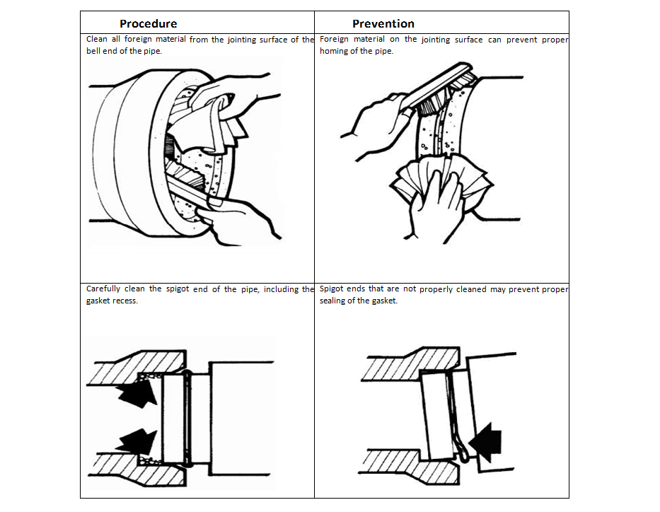
For all gasket types, dirt, dust, and foreign matter must be
cleaned from the joint surfaces. Except for pre-lubricated
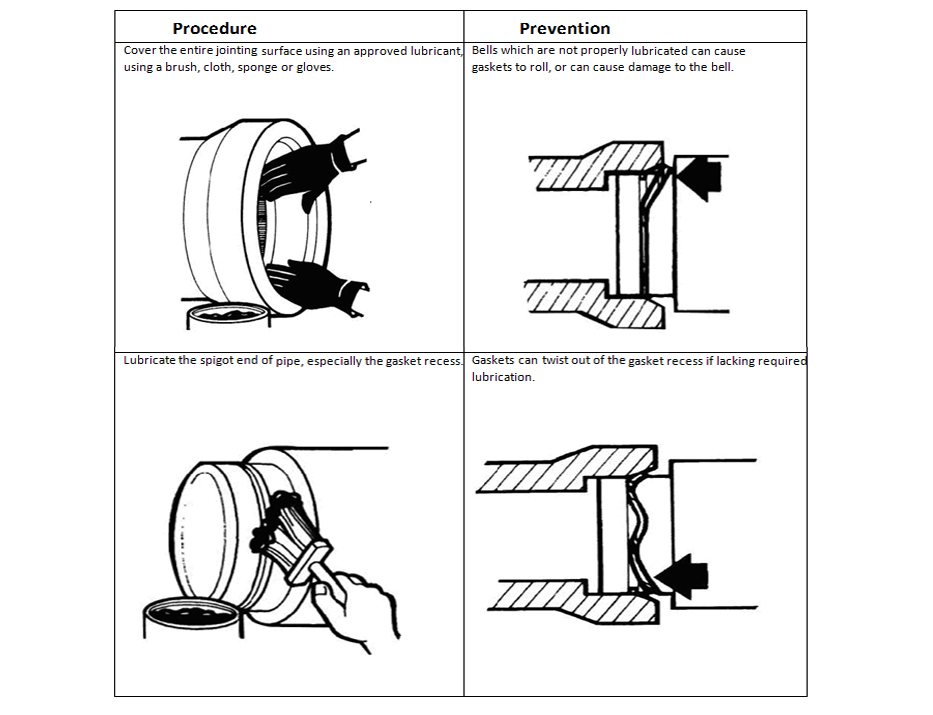
type, the gasket and bell should be coated with a lubricant
recommended by the manufacturer. The lubricant must be clean
and be applied with a brush, cloth pad, sponge or glove. In
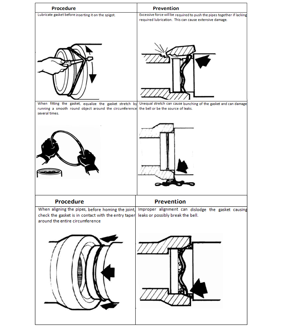
some cases, a smooth round object, such as a Screwdriver shaft
should be inserted under the gasket and run around the
circumference two or three times, to equalize the stretch in
the gasket, before jointing.
Rubber gaskets are required to be stored in a sheltered cool
dry place. They need to be protected from prolonged exposure
to sunlight, extreme heat in the summer, and extreme cold in
the winter. Proper care of the gaskets prior to the
installation will ensure maximum ease of installation, and
maximum sealing properties. Gaskets are generally formulated
for maximum sealing performance in a standard sewer
installation carrying Primarily storm water or sanitary
sewage. Custom rubber formulations are available for special
situations, where specific elements are being carried in the
effluent. Some common examples of where a custom formulation
would be required are where resistance is needed against
hydrocarbons, acids, UV rays, ozone, and extreme heat.
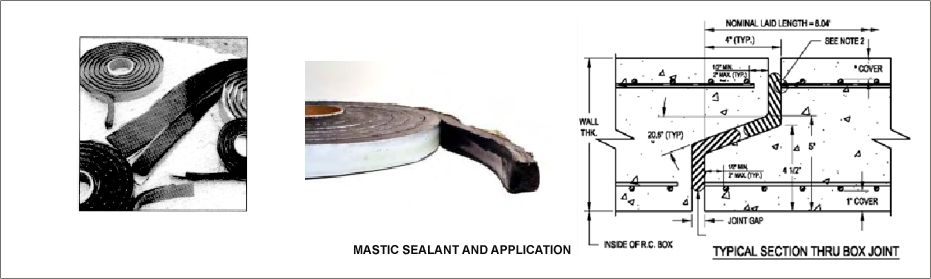
Mastic Sealant Jointing
Mastic sealants consist of bitumen or butyl rubber and is usually
cold applied. The joint surfaces must be thoroughly cleaned, dried
and prepared in accordance with the manufacturer's
recommendations.
Typically supplied in pre-formed coils, the flexible rope style
sealant should be properly sized based on the width of the annular
joint space being sealed.
During cold weather, better workability of the mastic sealant can
be obtained if the mastic and joint surfaces are warmed.
Mortar
Mortar for joints is composed of one part normal Portland cement
and two parts mortar sand, wetted with only sufficient water to
make the mixture plastic.
The joint surface is thoroughly cleaned and soaked with water
immediately before the joint is made. A layer of mortar is placed
in the lower portion of the bell end of the installed pipe and on
the upper portion of the spigot end of the pipe section to be
installed. The spigot is then inserted into the bell of the
installed pipe until the sealant material is squeezed out. Any
annular space within the pipe joint is filled with mortar, and the
excess mortar on the inside of the pipe is wiped and finished to a
smooth surface.
Regardless of the specific joint sealant used, each joint should
be checked to be sure all pipe sections are in a homed position.
For joints sealed with rubber gaskets, it is important to follow
the manufacturer's installation recommendations to ensure that the
gasket is properly positioned, and is under compression.
External Bands
External bands may be used in addition to any jointing material to
serve two functions:
- Prevent fine materials from entering the joint
- Prevent infiltration of groundwater
If the prevention of bedding material from entering the
conveyance system is the primary objective, filter fabric,
while allowing the groundwater to infiltrate, will stop the
bedding backfill material from entering.
To prevent the infiltration of water, external extruded rubber
gaskets are utilized. The gasket must be of sufficient width
to cover the joint, and must be installed with some tension
applied, according to the manufacturer's recommendations. As
the joint is backfilled, pressure is applied to the gasket as
it is pressed against the structure, providing a seal at the
joint.
Jointing Procedures
Joints for pipe sizes up to 600 mm in diameter can usually be
assembled by means of a bar and wood block. The axis of the pipe
section to be installed should be aligned as closely as possible
to the axis of the last installed pipe section, and the tongue, or
spigot, end inserted slightly into the bell, or groove. A bar is
then driven into the bedding and wedged against the bottom bell,
or groove, end of the pipe section being installed. A wood block
is placed horizontally across the end of the pipe to act as a
fulcrum point, and to protect the joint end during assembly. By
pushing the top of the vertical bar forward, lever action pushes
the pipe into a home position.
When jointing medium diameter pipe, a chain or cable is wrapped
around the barrel of the pipe behind the tongue, or spigot, and
fastened with a grab hook, or other suitable connecting device. A
lever assembly is anchored to the installed pipe, several sections
back from the last installed section, and connected by means of a
chain, or cable, to the grab hook on the pipe to be installed. By
pulling the lever back, the tongue, or spigot, of the pipe being
jointed is pulled into the bell, or groove, of the last installed
pipe section. To maintain close control over the alignment of the
pipe, a laying sling can be used to lift the pipe section slightly
off the bedding foundation.
When jointing larger diameter pipe, and when granular bedding is
used, mechanical pipe pullers are required. Several types of pipe
pullers, or "come along" devices, have been developed, but the
basic force principles are the same. Large diameter pipe can be
joined by placing a "dead man" block inside the installed pipe,
several sections back from the last installed section, which is
connected by means of a chain or cable to a strong back placed
across the end of the pipe section being installed. The pipe is
pulled home by lever action similar to the external assembly.
Mechanical details of the specific apparatus used for pipe
pullers, or come along devices, may vary, but the basic lever
action principle is used to develop the necessary controlled
pulling force. Note: The excavating equipment must not be used to
push pipe sections together or to adjust pipe to the final grade.
The force applied by such equipment can damage pipe joints.
Summary of Jointing Procedures for Pre- lubricated Gasket for
Single Offset Joints
The unique design of the pre-lubricated pipe gasket requires no
field lubrication and no equalization after installation.
Installation:
1. Ensure that bell and spigot are free from cracks, chips, or
other defects.
2. Brush loose dirt, debris and foreign material from the inside
surface of the bell, the spigot and the gasket.
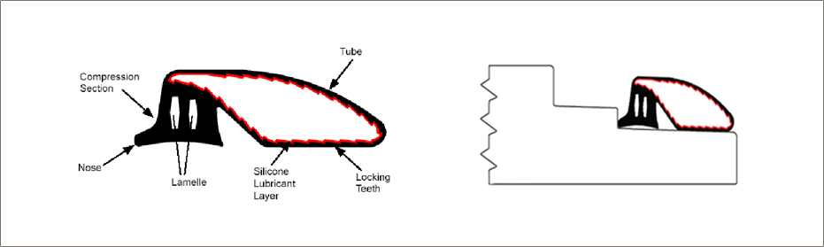
3. Stretch gasket around the spigot, with the nose against the
step, and the tube laying flat against the spigot.
4. Align the spigot with the bell, and thrust the spigot home
using suitable mechanical means. The Homing process will cause the
lubricated tube to "roll" over itself, above the compression
section, allowing the pipe to slide forward.
Once the pipe is fully homed,
- The compression section seals the total annular space
-
The rolling tube comes to rest within the small annular
space � acting as a cushion against side loads
- The serrations act to resist pipe pull-out.
Summary of jointing procedure of Rubber Gasket
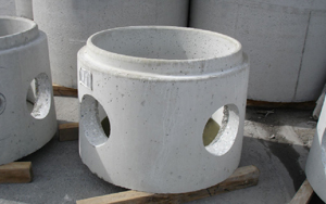
Service Connections
Service connections to the main pipe sewer should be made using
factory made tees or wyes, strap-on-saddles, or other approved
saddles. Factory made tees or wyes should be used for all service
connections where the diameter of the main pipe sewer is:
- Less than 450 mm, or
-
Less than twice the diameter of the service connection.
Holes in the main pipe sewer should be cut with approved cutters
and should be the minimum diameter required to accept the service
connection. If mortar-on saddles are used, the inside of the pipe
should be mortared at the connection.
Where existing service connections are to be connected to new pipe
sewers or service connections, proper jointing procedures must be
used.
Changes in Alignment
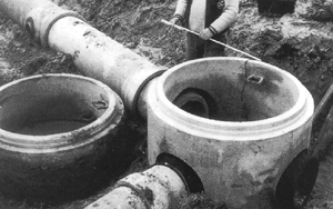
Maintenance holes should be used when there is a need to change
alignment, grade or size of a pipeline. Alignment
Changes in concrete pipe sewers can also be incorporated into the
line through the use of deflected straight pipe, radius pipe, or
bends. Since manufacturing and installation feasibility are
dependent on the particular method used to negotiate a curve, it
is important to establish the method prior to excavating the
trench.
-
For deflected straight pipe, the joint of each pipe section
is opened on one side while the other side remains in the
home position. The difference between home and opened joint
space is generally designated as the pull. The maximum
permissible pull must be limited to that opening which will
provide satisfactory joint performance. This varies for
different joint configurations and is best obtained from the
pipe manufacturer.
-
When establishing alignment for radius pipe, the first
section of radius pipe should begin one half of a radius
pipe length before the beginning of curve, and the last
section of radius pipe should extend one half of a radius
pipe length beyond the end of curve.
-
When extremely sharp curves are required, deflected straight
pipe or radius pipe may not be suitable. In such cases,
bends or elbows may be used.
One or more of these methods may be employed to meet the most
severe alignment requirements. Since manufacturing processes and
local standards vary, local concrete pipe manufacturers should be
consulted to determine the geometric
Key Notes & Precautions
-
Improper bedding: Most joint annular spaces
are �-inch to �-inch. If the bedding is irregular, lining up
the Bell with the receiving Spigot will be difficult.
-
Use of granular material with an excess percentage of
fines:
If the trench is wet, the fines will not provide a stable
work area.
-
Standing water in the trench: It is
difficult to judge the grade and uniformity of the granular
bedding, to properly dig an adequate groove hole, and to
ensure that no dirt or granular material is in the groove
when water is standing in the trench.
-
Pulling the pipe into the home position unevenly:
Care should be taken to ensure that both portions of the
Bell get started evenly into the Spigot of the previously
set Pipe.
-
Ensure that adequate inspection / examination and
maintenance of the equipment have been carried out prior to
its use.
-
The crane or lifting equipment operator should be competent
and suitably trained and must be experienced to carry out
all relevant duties.